
 By Richard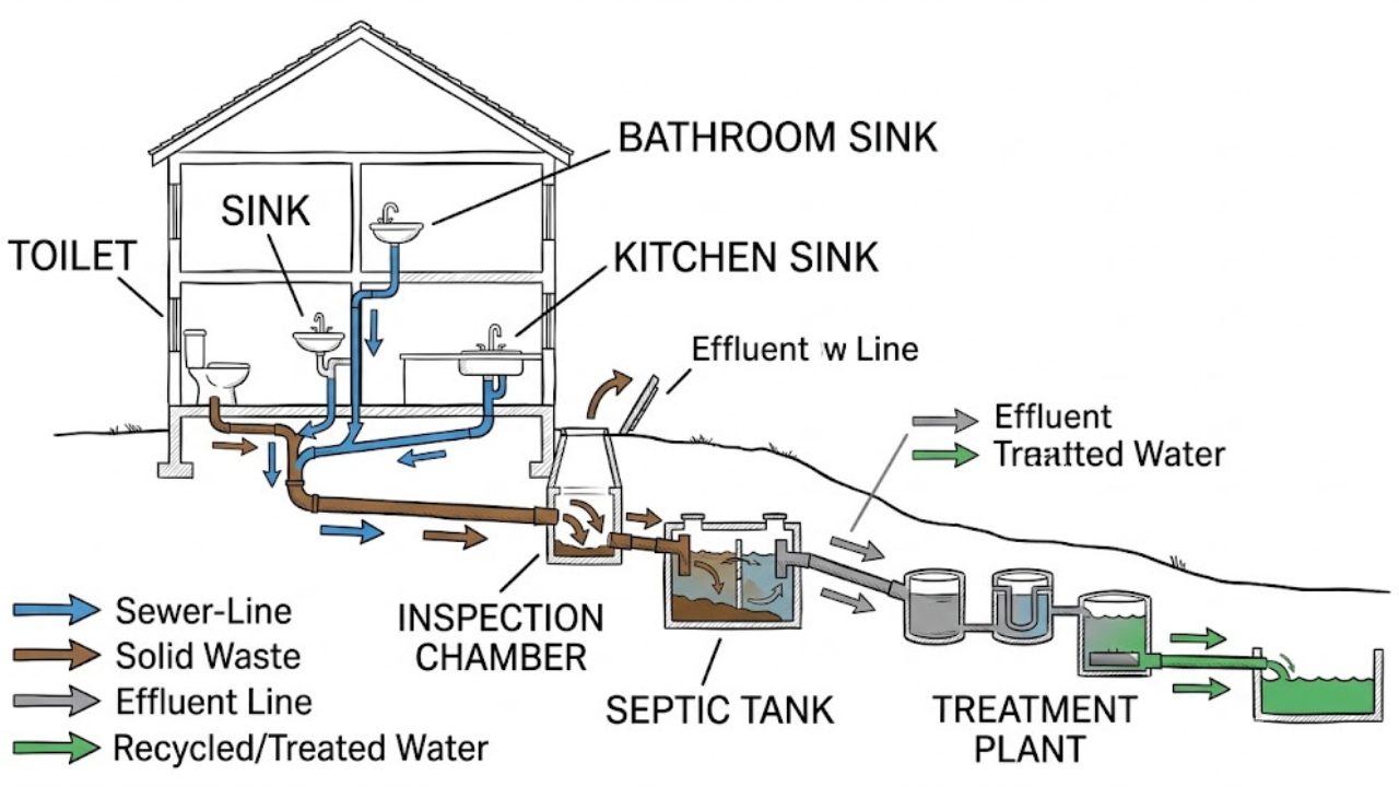
Introduction
Have you ever wondered where wastewater goes after you flush a toilet? A well-planned sewer drawing turns that hidden journey into a clear visual story, showing pipes, drains, tanks, treatment units, and the final outlet.
Whether you enjoy technical sketches or want to create an accurate illustration for your portfolio, this guide will help you understand sewer diagrams without complicated engineering language. You will learn how to make a sewer drawing easy, identify the main types of sewer drawing, add color effectively, and sketch both a residential sewer system diagram and a sewage system diagram on ship.
You will also discover how piping layout drawings work, what a simple sewage system drawing includes, and how to avoid common mistakes. By the end, you can create a clean, educational diagram that looks attractive while remaining technically understandable. Keep your pencil, ruler, colored markers, and imagination ready—your next sketch starts with a line showing the direction of flow.
Table of Contents
-
What Is a Sewer Drawing?
-
Why Does a Sewer Drawing Matter?
-
Sewer Drawing: Key Facts and Types
-
How to Create a Sewer Drawing
-
Common Sewer Drawing Mistakes to Avoid
-
Expert Tips for Better Sewer Drawings
-
Frequently Asked Questions About Sewer Drawing
What Is a Sewer Drawing?
A sewer drawing is a visual representation of a system that collects, carries, and treats wastewater. It may show household drains, underground sewer pipes, inspection chambers, pumping stations, septic tanks, treatment plants, or discharge points.
Think of it as a road map for dirty water. Roads carry cars from homes to destinations; sewer pipes carry wastewater from toilets, sinks, showers, and industrial areas to a treatment or storage point. Arrows show the direction of movement, while labels explain each part.
A basic drawing may include a toilet connected to a soil pipe, a branch drain leading to a main sewer, and a treatment plant at the end. More advanced diagrams add pipe sizes, slopes, elevations, valves, vents, manholes, and flow rates.
For artists, the goal is not always engineering approval. Your goal may be to create an understandable visual guide. Even so, correct flow direction and logical connections make your artwork more convincing.
Why Does a Sewer Drawing Matter?
A clear sewer sketch helps people understand a system that usually remains underground or hidden behind walls.
-
It explains invisible infrastructure. A diagram makes wastewater movement easy to follow.
-
It supports planning. Builders and plumbers use layouts to locate pipes, access points, and fixtures.
-
It improves learning. Students can understand sanitation better through a labeled visual than through text alone.
-
It makes problems easier to spot. Blockages, missing vents, poor connections, or incorrect flow directions become visible.
-
It adds visual interest. A sewer drawing with colour can turn a technical subject into engaging artwork.
The U.S. Environmental Protection Agency reports that wastewater treatment protects public health and keeps pollutants from entering rivers, lakes, and coastal waters. In the maritime sector, MARPOL Annex IV requires regulated ships to have an approved sewage treatment plant, comminuting and disinfecting system, or holding tank.
Sewer Drawing: Key Facts and Types
A good diagram begins with the right system type. Each layout has a different purpose, scale, and level of detail.
Residential Sewer System Diagram
A residential sewer system diagram shows how wastewater leaves a house. Fixtures connect to smaller branch pipes, which join a larger building drain. That drain then connects to a municipal sewer or a private septic tank.
A simple layout usually includes:
-
Toilets and bathroom fixtures.
-
Kitchen and laundry drains.
-
Vent pipes.
-
Building drain.
-
Cleanouts or inspection chambers.
-
Public sewer or septic tank.
Combined and Separate Sewers
A separate sewer system carries sanitary wastewater in one pipe and stormwater in another. A combined system carries both through the same network, which can create overflow risks during heavy rain.
Sewage System Diagram on Ship
A sewage system drawing on ship shows toilets and accommodation spaces connected to collection lines. Wastewater may travel to a treatment plant, a holding tank, or a comminuting and disinfecting unit.
Ship diagrams often include pumps, vacuum toilets, vents, alarms, discharge connections, and storage tanks. International maritime rules restrict untreated sewage discharge near land, so the diagram should clearly show storage and treatment stages.
Gravity and Pumped Systems
Gravity systems depend on pipe slope to move wastewater downward. Pumped systems use lifting stations when terrain, ship structure, or building levels prevent natural flow.
A sewage system drawing simple enough for beginners should use three visual levels: source, transport, and destination. This structure keeps the drawing readable.
How to Create a Sewer Drawing
Follow these steps to make a clean and understandable sketch.
1. Choose the system
Decide whether you want to draw a house, apartment block, city network, ship, or treatment plant. A small subject makes a sewer drawing easy and prevents unnecessary detail.
Write the system name at the top of your page. This keeps your design focused.
2. Mark the wastewater sources
Draw toilets, sinks, showers, floor drains, or ship cabins first. Use simple symbols rather than detailed furniture.
Place each source where it would logically appear. For a house, group bathroom fixtures together and place the kitchen drain near the kitchen area.
3. Add branch pipes
Connect every fixture to a smaller branch pipe. Keep the lines neat and avoid crossing them unless the crossing has a clear meaning.
Use different line weights if you work in black and white. Thin lines can represent branches, while a thicker line can represent the main drain.
4. Draw the main sewer route
Join the branches to a larger pipe or collection line. Add arrows to show wastewater movement from each fixture toward the outlet.
For a gravity system, show a gentle downward slope. For a ship or flat site, include a pump symbol where mechanical lifting is required.
5. Add treatment or storage
Finish the route with a septic tank, municipal treatment plant, holding tank, or ship sewage treatment unit. Divide the tank into sections if you want to show settling, biological treatment, and discharge.
A simple tank can be drawn as a rectangle with internal partitions. Label each section clearly.
6. Include vents and access points
Add vent pipes above building drains and inspection chambers along underground routes. These details make a residential sewer system diagram more realistic.
Do not overcrowd the page. Include only the components that help explain the system.
7. Add colour and labels
Use blue for clean water, brown or dark gray for wastewater, green for treated water, and red for warning or restricted discharge. A sewer drawing with colour should use a small, consistent palette.
Add a legend explaining every colour and symbol. Finish with a title, arrows, and a note such as “Not to scale” if the sketch is educational rather than architectural.
Common Sewer Drawing Mistakes to Avoid
-
Drawing pipes without flow arrows. The viewer cannot tell where wastewater travels. Add arrows at bends, junctions, and major stages.
-
Mixing clean water and sewage colours. Use a clear legend so blue does not accidentally represent wastewater.
-
Connecting every fixture to one oversized line. Real systems use branch drains that gradually join larger pipes.
-
Ignoring access points. A diagram without cleanouts, manholes, or inspection chambers feels incomplete.
-
Showing treatment as a single mystery box. Label the main stages so viewers understand what happens inside.
-
Treating ship and residential systems as identical. Ships often need holding tanks, pumps, alarms, and approved treatment equipment because discharge conditions differ.
Expert Tips for Better Sewer Drawings
-
Start with pencil guides. Light construction lines help you correct spacing before adding ink or colour.
-
Use a visual hierarchy. Make the main sewer line thicker than secondary branches and use larger labels for major units.
-
Keep flow left to right. This reading direction makes a technical diagram easier to follow.
-
Use colour sparingly. Three or four meaningful colours usually communicate more clearly than a rainbow palette.
-
Add a scale note. If your drawing is artistic or educational, write “Diagrammatic—not to scale” to prevent confusion.
-
Check every connection. Trace the system backward from the outlet to confirm that each source has a logical route.
-
Leave white space. Empty areas separate labels and stop your drawing from becoming visually noisy.
Frequently Asked Questions About Sewer Drawing
What is piping layout drawing?
A piping layout drawing shows the position and route of pipes, fittings, valves, equipment, and access points within a building or facility. It may use a plan view, elevation, or isometric view. In a sewer sketch, the layout focuses on wastewater flow, pipe connections, slopes, fixtures, vents, and treatment or discharge points. Piping drawings commonly identify the location, size, and type of piping used.
What is sewers class 7?
In Class 7 science, sewers are usually explained as underground pipes that carry wastewater and human waste away from homes, schools, and other buildings. Students learn that sewage travels through a drainage network to a sewage treatment plant, where solids and harmful pollutants are removed. A labeled sewage system drawing simple enough for a classroom often shows a house, sewer pipe, treatment plant, and cleaned water outlet.
How do you draw a pipe sketch?
Begin by selecting the view: side, top, or isometric. Draw the main pipe route first, add branches and fittings, place arrows for flow, and label important parts. Use a ruler for straight runs and curved templates for bends. For a more attractive result, outline the finished drawing with a fine pen, then apply a limited colour code. Always check that every pipe connects logically.
Conclusion
A successful sewer drawing does three jobs: it shows where wastewater begins, explains how it travels, and identifies where treatment or storage occurs. Start with a simple residential layout, use arrows and labels, then add colour to separate wastewater, treated water, and warning points.
You can also adapt the same method for a ship sewage diagram, municipal sewer map, or classroom illustration. Start today by drawing three boxes—source, pipe network, and destination—and connect them with clear lines. What type of sewer drawing will you sketch first?